
When lightning strikes a building, or a fault current runs through a transformer, the earthing system has one job: send that energy safely into the ground. How well it does that depends heavily on a property most people never think about until a design review asks for it, the resistivity of the soil. Earth resistivity testing measures that property, and it is the starting point for almost every reliable earthing design.
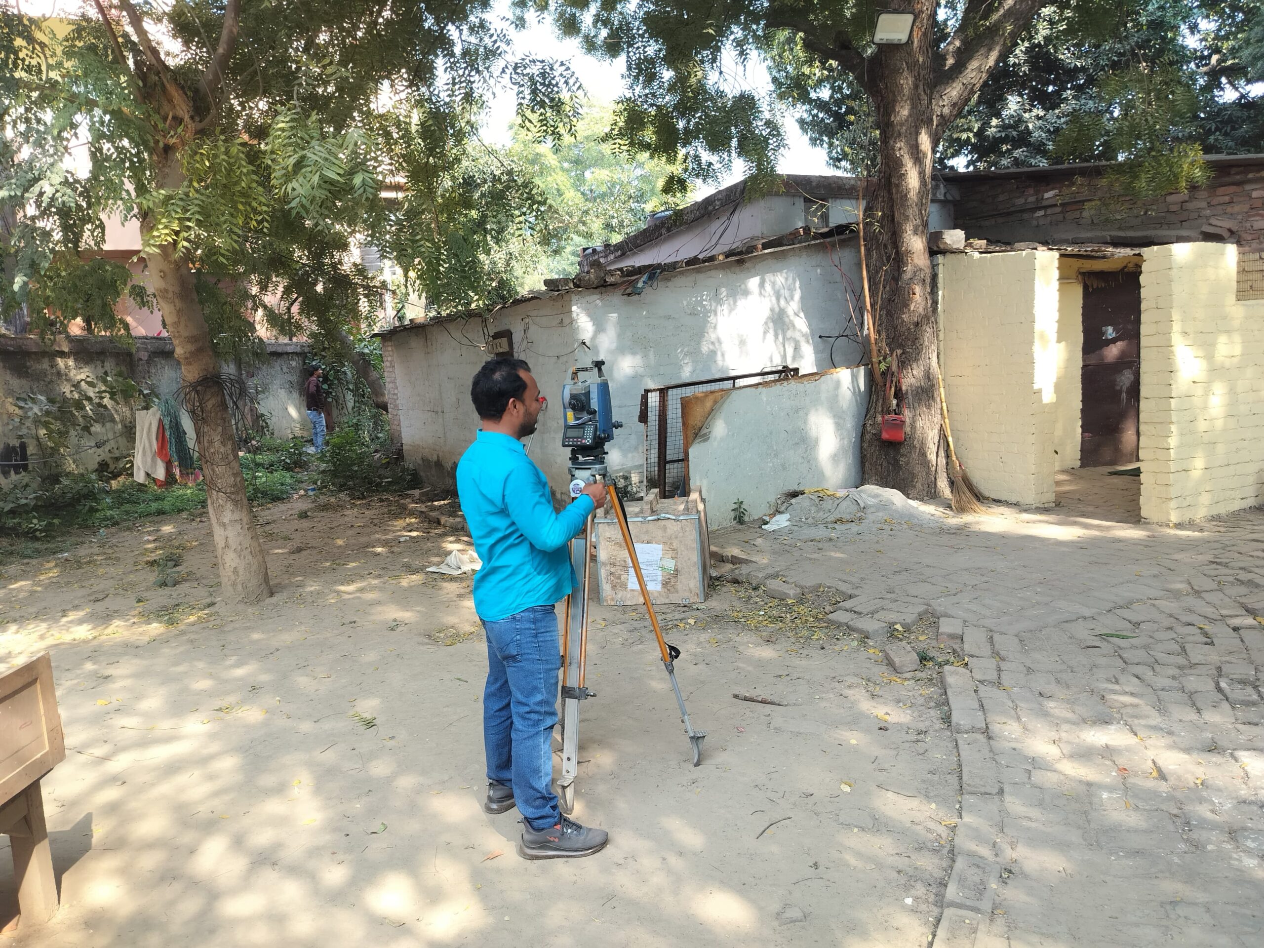
At RK Soil Testing LLP, our team in Gomti Nagar, Lucknow, works on geotechnical and site investigation projects across Uttar Pradesh, and earth resistivity surveys regularly sit alongside soil investigation for industrial, power, solar and infrastructure sites. This guide explains what the test is, how it is carried out in the field, how to read the results, and the mistakes that most often spoil them.
What Is Earth Resistivity Testing?
Earth resistivity (also called soil resistivity) is a measure of how strongly the ground resists the flow of electric current. It is expressed in ohm-metres (Ω·m). A low value means the soil conducts well; a high value means it resists current.
Earth resistivity testing is the field measurement of this property. A known current is passed through the ground between electrodes, the resulting voltage is measured between other electrodes, and the instrument calculates a resistance that is then converted into resistivity using the electrode spacing. Because the ground is rarely uniform, the value obtained is called apparent resistivity, and by repeating the measurement at different spacings, we learn how resistivity changes with depth.
Soil resistivity is different from earth electrode resistance. Resistivity is a property of the ground itself. Electrode resistance is the performance of a particular earthing rod, plate or grid installed in that ground. The first is measured before design; the second is checked after installation.
Why Earth Resistivity Testing Is Important
Safe and economical earthing design. The resistivity of the soil decides how many electrodes, how much conductor length and what layout are needed to reach the required earth resistance. Without a measured value, designers are forced to assume, which leads to either under-designed systems that fail to protect, or over-designed ones that waste money.
Protection of people and equipment. A poorly designed earthing system can allow dangerous step and touch voltages during a fault. Accurate soil data lets the designer limit them to safe levels.
Lightning protection. Lightning protection systems depend on dispersing very high, very fast currents into the ground. Soil with high resistivity needs a more carefully planned earth termination.
Power, solar and telecom sites. Substations, transformers, solar plants, transmission towers, telecom towers and data centres all need soil resistivity data for earthing design, and utilities and consultants usually ask for it in project specifications.
Corrosion assessment. Low-resistivity soil is generally more corrosive to buried steel, pipelines and cables. Resistivity is therefore used to judge corrosion risk and to plan cathodic protection.
Groundwater and geophysical investigation. Resistivity surveys are also used to estimate soil layering, depth to rock and the presence of water-bearing zones, because different materials conduct differently.
What Affects Soil Resistivity?
Resistivity is not a fixed number for a location. It changes with:
- Soil type: Wet clay and silt generally show low resistivity, while dry sand, gravel and rock show high resistivity. Values can range from a few ohm-metres in wet saline soil to several thousand in dry rocky ground.
- Moisture content: This is usually the biggest factor. Wetter soil conducts better.
- Dissolved salts and minerals: More ions in the pore water lower resistivity.
- Temperature: Resistivity rises sharply when soil freezes and is also affected by heat and drying.
- Compaction and density: Better particle contact generally lowers resistivity.
- Season: Monsoon and dry season readings can differ greatly, so the time of testing matters.
This is why a resistivity report should always record the date, weather, recent rainfall and ground condition at the time of measurement.
Methods of Earth Resistivity Testing
1. Wenner Four-Pin Method
The Wenner method is the most widely used field method. Four electrodes are driven into the ground in a straight line at equal spacing a. A current is injected through the two outer electrodes, and the voltage is measured between the two inner ones. The apparent resistivity is calculated as:
ρ = 2π × a × R
where ρ is the apparent resistivity in Ω·m, a is the electrode spacing in metres, and R is the resistance reading from the instrument in ohms.
As a practical rule, the resistivity measured at spacing a mainly reflects the soil down to a depth of about the same order as a. By repeating the test at spacings such as 1 m, 2 m, 4 m, 8 m, 16 m and beyond, a profile of resistivity against depth is built up.
2. Schlumberger Method
In the Schlumberger arrangement, the inner (potential) electrodes stay fixed and close together while the outer (current) electrodes are moved progressively outward. It requires fewer electrode movements for deep readings and is common in geophysical and groundwater work, especially where deeper profiling is needed.
3. Other Arrangements
Variations such as the driven-rod (three-point) method are used for specific situations, and electrical resistivity tomography (ERT) uses many electrodes and software to produce two-dimensional sections of the ground for detailed investigation. The choice depends on the purpose, the depth of interest and the site conditions.
Field Procedure: How the Test Is Actually Done
The steps below describe a typical Wenner survey. Specific requirements should follow the project specification and the applicable standards, such as IS 3043 for earthing practice and IEEE Std 81 for measuring earth resistivity.
Step 1: Site Study and Planning
Before going to the field, we review the site layout, the area available for survey lines, buried services such as pipes and cables, and the depth that matters for the design. We also decide the number of survey lines and their directions.
Step 2: Laying Out the Survey Line
Four electrodes are placed in a straight line at equal spacing. The electrodes are driven to a shallow depth, and the usual guideline is that the depth should be small compared with the spacing, roughly one-twentieth or less, so that the calculation remains valid.
Step 3: Connecting the Instrument
Leads are connected to a four-terminal earth resistance tester. Leads are kept apart and not coiled, to avoid unwanted coupling between them. Contact between the electrode and soil is checked, and the instrument is verified to be within calibration.
Step 4: Taking Readings at Multiple Spacings
The spacing is increased step by step, with the whole line re-laid symmetrically about the same centre point. The resistance at each spacing is recorded together with the spacing.
Step 5: Repeating in Other Directions
Readings are repeated along a line at right angles to the first, and at other locations on larger sites. A single line can mislead because of local features, so multiple directions and locations give a more reliable picture.
Step 6: Calculation and Interpretation
Apparent resistivity is calculated for each spacing and plotted against spacing. The curve is then interpreted, often using a two-layer or multi-layer soil model, to give design values for the top layer, the deeper layer and the layer boundary. Specialist earthing design software commonly uses this model.
Understanding the Results
A resistivity report is useful when it tells the designer what to do. Typical outputs include:
- A table of spacing, resistance and apparent resistivity for each survey line
- A curve of apparent resistivity versus spacing
- An interpreted soil model, giving resistivity and thickness of each layer
- Notes on weather, soil moisture and any site disturbance
- Recommendations for earthing design, such as the need for deeper electrodes, additional rods, chemical or enhanced earthing compounds, or ground improvement where resistivity is high
If the top layer has high resistivity but a lower layer is much better, deeper electrodes may be the most effective answer. If the whole profile is high, a larger grid, more conductor length or treatment of the soil may be needed. If it is very low, corrosion protection may become the more important concern.
Common Mistakes That Lead to Wrong Results
- Testing near buried metal. Pipes, cables, fences and rebar can carry current and distort readings. Survey lines should be kept away from buried metallic structures, or run at right angles to them.
- Using too few spacings. If the deeper layers are not tested, the design may rest on assumptions about the soil that matter most.
- Surveying in only one direction. Local variation then goes unnoticed.
- Poor electrode contact. Dry, stony or loose ground can give unstable readings. Wetting around the electrode or re-driving it may be needed.
- Ignoring season and weather. A reading taken after heavy rain may be much lower than the dry-season condition that governs worst-case design. Always record conditions.
- Coiled or touching leads and uncalibrated instruments. Both can introduce errors that are hard to detect later.
- Treating one number as the answer. The soil is layered and changes with depth, so the interpretation is as important as the measurement.
When Should You Get Earth Resistivity Testing Done?
- Before designing the earthing system of a building, factory, substation, transformer yard or solar plant
- Before installing lightning protection for tall or critical structures
- For telecom towers, transmission lines and other utility projects
- When an existing earthing system shows high resistance or poor performance
- When planning pipelines, tanks or buried steel where corrosion is a concern
- For groundwater exploration and subsurface profiling
- When a consultant, utility, or tender document requires a soil resistivity report
Testing before design is far cheaper than redesigning or retrofitting earthing after construction.
Why Choose RK Soil Testing LLP
RK Soil Testing LLP provides geotechnical investigation, building material testing, topographical surveys and chemical analysis from our Lucknow laboratory, and has supported projects across Uttar Pradesh for over 25 years. Our team handles field investigation as well as laboratory work, so your site data can come from one coordinated source.
What you can expect from us:
- A survey plan suited to your site and design requirement
- Field measurements by trained personnel using calibrated equipment
- Clear reporting of readings, curves and interpreted soil layers
- Practical comments that help the designer choose the earthing approach
- Coordination with geotechnical and chemical testing when required, since soil chemistry and moisture influence resistivity
You can read about our geotechnical investigation work and our chemical analysis services, or contact our team to discuss your project.
Frequently Asked Questions
What is the unit of earth resistivity?
What is the difference between earth resistivity and earth resistance? Resistivity is a property of the soil itself. Earth resistance is the resistance offered by a specific electrode or earthing system installed in that soil.
Which method is most commonly used? The Wenner four-pin method is the most common for earthing design, while the Schlumberger method is more common in geophysical and groundwater surveys.
What is the best time to test? There is no single best time. Dry-season testing shows the conservative, high-resistivity condition, while a test after rain shows a more favourable condition. Recording the conditions and, where needed, testing in more than one season gives the designer the full picture.
How deep does the test measure? Roughly, the depth of investigation is of the same order as the electrode spacing, so larger spacings reflect deeper soil.
Can resistivity be reduced if the soil is poor? Yes, options include deeper or additional electrodes, a larger earthing grid, and soil treatment or enhanced earthing materials. The right choice should come from the design calculation, not guesswork.
Do I need this test for a small building? Smaller buildings may use simpler earthing arrangements, but where the earthing requirement is critical, the soil is difficult, or a specification asks for it, a resistivity test is worthwhile.
Conclusion
Earth resistivity testing replaces assumption with measurement. It tells the designer how the ground will behave under fault and lightning current, how that behaviour changes with depth and season, and what kind of earthing system will actually achieve the required protection. Done carefully, with proper spacings, multiple directions and thoughtful interpretation, it supports safer installations and avoids costly rework.
If you are planning an earthing system or a site investigation in Lucknow or elsewhere in Uttar Pradesh, RK Soil Testing LLP can help. Call +91-9336177365 or +91-63942 31419, or visit our laboratory at 1/416 Vastu Khand, Gomti Nagar, Lucknow.
